Sensor installation - Battery/ATEX sensors
For installations in ATEX environments, please also read the manual of
the CanaryEx carefully.
There are important instructions regarding operating conditions,
earthing, installer qualifications and other more detailed input that is
important for a safe installation.
These are not included in this high-level installation overview, because
the purpose of this document is to provide a high-level introduction to
the installation, without diving into the details.
These installer instructions cannot be seen as a replacement of the
Canary EX user manual (for ATEX sensor)
Step-by-step instructions for installing sensors
Installing using the motor fin clamps
Attach the motor fin clamp to the motor such that the closing plate
and sensor can be easily mounted on it.
1. Determine the motor fins between which the distance
corresponds to the width of the clamp. If necessary, you can
tighten and narrow the clamp with a pair of pincers.
2. Degrease selected motor fins, after inquiring whether this is
possible and safe.
3. Add glue throughout the gutter of the motor fin clamp and
gently tap it onto a motor fin with a hammer.
4. You can now screw the mounting pad on the motor fin clamps
using the supplied screw
Nut-mounting approach
Follow the same steps as the standard installation while keeping three things into
account:
1. Ensure to wait until the bolt-adapter is firmly attached and the glue is set,
otherwise you are not able to firmly fixate the nut-mount to the adapter
2. You can adjust the orientation of the sensor easily, after you have loosely attached
the nut to the bolt-adapter
3. Fixate the bolt with a wrench / water pump pliers. Apply firm pressure. It is not
allowed to use glue to permanently fixate the sensor to the pad.
Tip: If you are not certain that the glue is set, use a second wrench to prevent the bolt
adapter from turning.
Optional: When the nut-mount is used in combination with a motor fin clamp, you can
use a screw to attach it to the motor fin clamp. You may glue to fixate this connection.
Steps to check connectivity
1. Quick press the button
2. If the light is not solid green:
3. Press and hold the button for 10 seconds
a. Release when the red-light blinks six times
4. Install the sensor on the machine
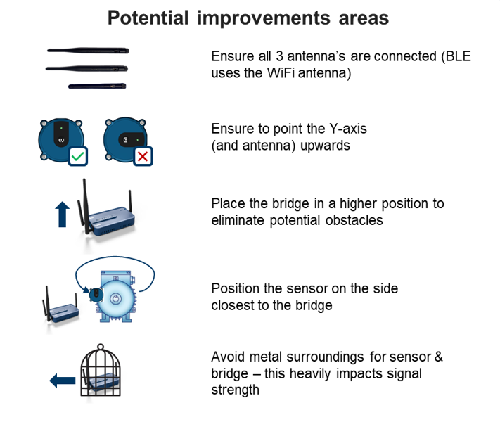
a. IMPORTANT: If the sensor is installed on the side of a motor, the orientation of the axes
marked on the housing must be respected
The Y axis must point upward (vertical)
The X axis must remain parallel to the ground (horizontal)
5. Make sure a Bridge is installed and within valid distance range
6. Press and hold the button for 3 seconds
7. The LED will blink green three times
8. Wait 30 seconds to perform the next step (WARNING: This delay is important. If the next step is
done after 60 seconds, the test will be invalid)
9. Quick press the button again, you will see the LED for 2 seconds:
a. Green light: Sensor is back in operations & connection has been established - you can
check the connection strength in the app
b. Orange blinking: Sensor is trying to connect, but no connection yet - test again after 10 & 20
seconds (after 30 seconds you need to go back to step 6)
c. Solid orange: Sensor and bridge are sending data - This is also a successful outcome, you
can check the connection strength in the app
10. If needed, adjust the distance between the bridge and the sensor to get a successful connection
Bridge connectivity